Things I kept in mind:
1. Lining things up is hard, so a one shaft option was preferred.
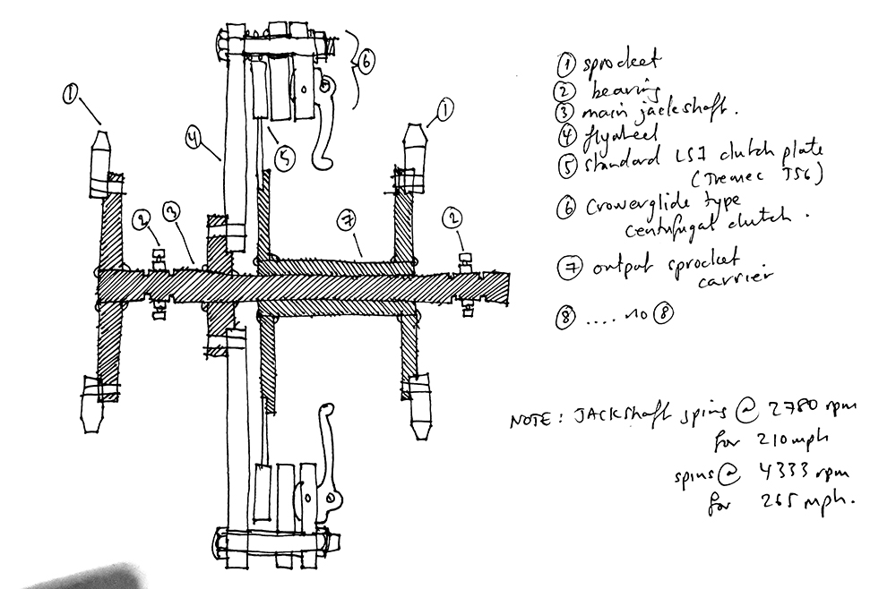
2. Making things is hard, so bolting it together and using as many off the shelf parts was preferred.
3. Specifying things is hard, so using parts that were designed to cope with the LS1 was preferred.
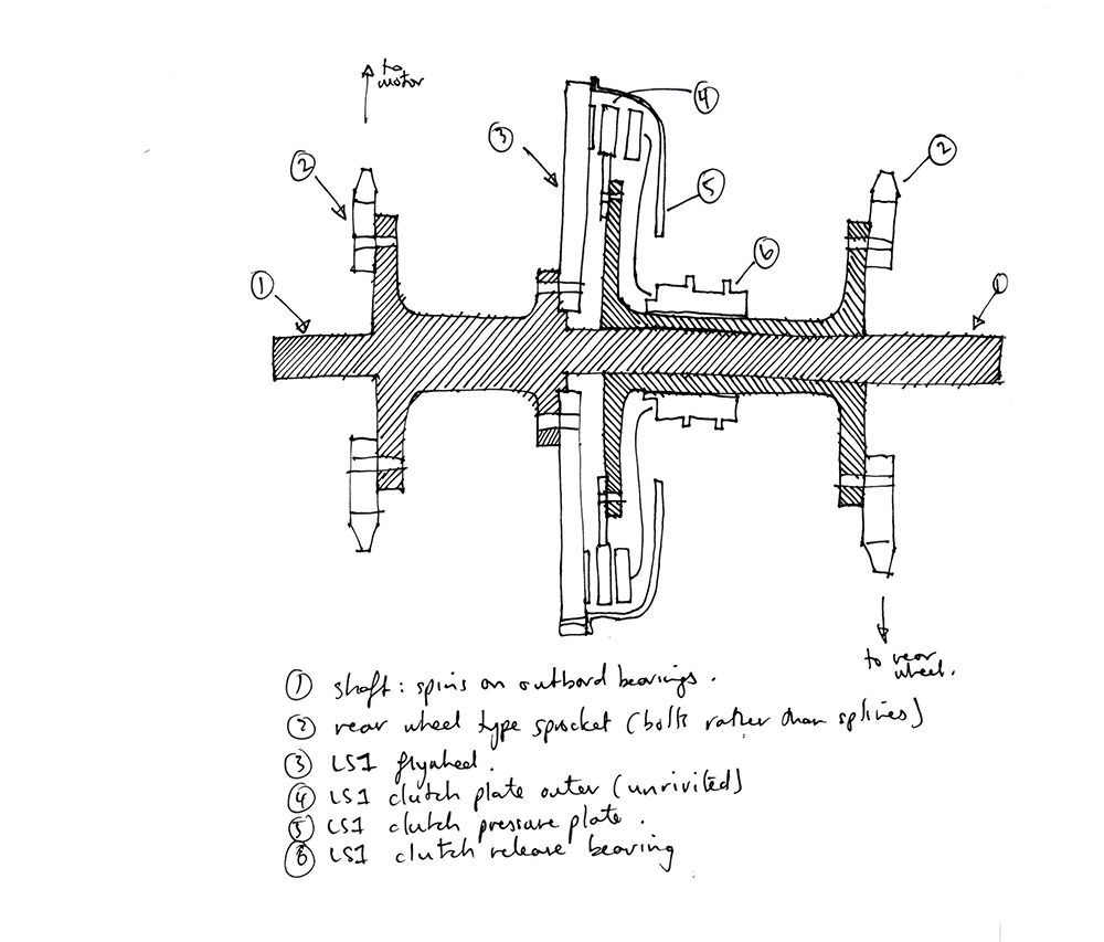
4. Remembering things is hard ... just realized I forgot to label the bit that carries the torque from the outer part of the LS1 clutch plate to the rear wheel sprocket carrier. The idea is that bit will spin with the main jackshaft so wont need a bearing between the two (but maybe a bronze bush).
The consequence of its sliding to the left as the clutch engages is that the rear chain will be misaligned when it is disengaged. As long as it's only a few mm out of alignment I don't think it will be a problem (of course that's what people who don't know say when they hope it won't be a problem!). I'm hoping to borrow an old clutch setup from my local mechanic to see if the measurements I'm thinking are feasible; the key one being the diameter of the diaphragm hole, so I can fit the slidy thing through it and still have a beefy shaft.
Using the larger rear sprockets (instead of the c17 tooth front splined sprockets) should give the chain an easier time as it turns through 180 degrees too.
Any comments/advice more than welcome, I'm certainly no engineer!