Very important to build in sufficient thrust bearing clearance. I used to run mine too close, (say 2-5mm) and had issues with clutch slip when hot. Be sure you have the clutch manufacturers spec on minimum clearance.
Chris
theTRUTH
Moderator: DLRA
Re: theTRUTH
Chris
-
russelllowe
- Posts: 252
- Joined: Mon Jan 06, 2014 2:21 pm
- Contact:
Re: theTRUTH
Hi Chris,
Will do. I might make the mount adjustable so if I find there is a problem I can move it around easily when we're on the salt.
Cheers
Will do. I might make the mount adjustable so if I find there is a problem I can move it around easily when we're on the salt.
Cheers
-
russelllowe
- Posts: 252
- Joined: Mon Jan 06, 2014 2:21 pm
- Contact:
Re: theTRUTH
Having a go at the jack shaft in Fusion 360; still not sure if I'm doing the assemblies right ... but here are all the components together ...
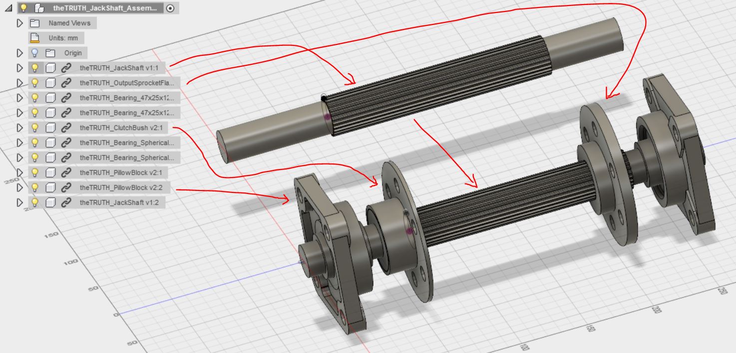
The whole thing is 300mm end to end, so not very long. It would be a little clearer if the clutch basket was in place but for reference that slips over and bolts to the clutch bush in the image above. Then the whole lot spins on two bearings that run on the non splined part of the shaft (the longer end to the left). I figured I should just use the same spline right the way through for simplicity ... but it does mean I'll need a custom sprocket carrier (I intend to use large diameter rear sprockets to give the chain an easier life anyway, so cutting a spline to suit regular motorcycle drive sprockets wouldn't really suit that idea) or I could rob the center out of a clutch plate and make an adapter to bolt between that and the sprocket.
I'll take this to the engineer later in the week and will report back.
Cheers
-
russelllowe
- Posts: 252
- Joined: Mon Jan 06, 2014 2:21 pm
- Contact:
Re: theTRUTH
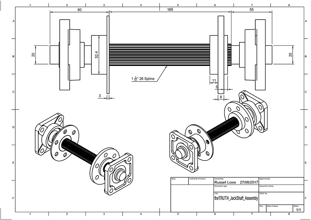
Handy when it makes the drawing for you ... (I had to add the dimensions which it would only do in orthographic views, which i thought was odd).
Cheers
Cheers
Re: theTRUTH
The ends of each spline must taper to a smooth join to the shaft. Your pic has a sharp point at the end of the spline, this is a stress riser and exactly were it will break.
Chris.
Chris.
Chris
-
russelllowe
- Posts: 252
- Joined: Mon Jan 06, 2014 2:21 pm
- Contact:
Re: theTRUTH
Hi Chris,
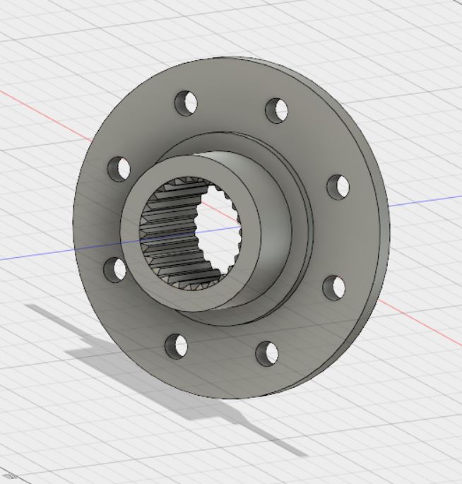
Cool, yeah sounds good ... the splines on this model are really just for visualization, I guessed at the actual shape of them (there are 26 though). I'll mention it to the gear maker.
Here is a model of the center of the clutch friction plate that came with the motor. I figure its got a couple of advantages over getting one made ... 1; I already have it and 2; it's been designed to cope with 430hp and however much torque the standard engine puts out so I can be sure it will do the job, for the first year at least.
And I thought this might be interesting, it's the original friction disk with the Quarter Master 7.25" disk sitting on top of it ... huge difference! I haven't done an area calculation but it's hard to imagine that the three Quater Master disks would have more area than the stock one.
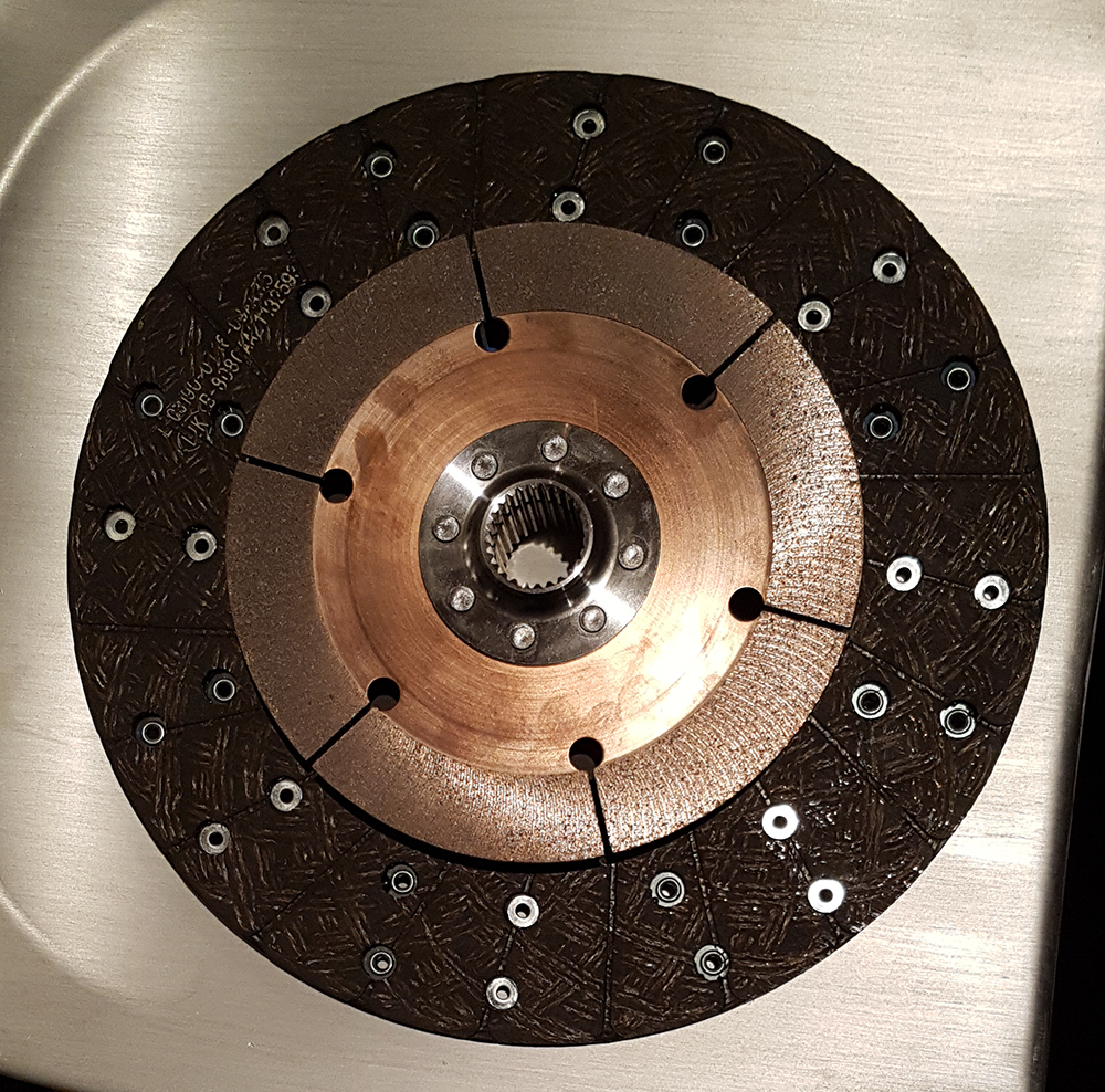
Ok, so I just did do the maths and the original disk is 81,208mm2 (counting both sides) while the Quarter Master disks are 81,640mm2 (counting all six sides). So almost identical. I thought the "grip" of a clutch was directly related to how friction much area it has ... is that right?
Maybe the smaller area allows the spring to exert more clamping force? I feel like I read that somewhere too ...
Anyway, there must be some difference because one has to deal with 430hp and the other is claimed to deal with 1,400hp.
Anyone know?
Cheers
Cool, yeah sounds good ... the splines on this model are really just for visualization, I guessed at the actual shape of them (there are 26 though). I'll mention it to the gear maker.
Here is a model of the center of the clutch friction plate that came with the motor. I figure its got a couple of advantages over getting one made ... 1; I already have it and 2; it's been designed to cope with 430hp and however much torque the standard engine puts out so I can be sure it will do the job, for the first year at least.
And I thought this might be interesting, it's the original friction disk with the Quarter Master 7.25" disk sitting on top of it ... huge difference! I haven't done an area calculation but it's hard to imagine that the three Quater Master disks would have more area than the stock one.
Ok, so I just did do the maths and the original disk is 81,208mm2 (counting both sides) while the Quarter Master disks are 81,640mm2 (counting all six sides). So almost identical. I thought the "grip" of a clutch was directly related to how friction much area it has ... is that right?
Maybe the smaller area allows the spring to exert more clamping force? I feel like I read that somewhere too ...
Anyway, there must be some difference because one has to deal with 430hp and the other is claimed to deal with 1,400hp.
Anyone know?
Cheers
Re: theTRUTH
We were taught when I was an apprentice, 'friction is independent of area'. Clamp pressure is it. Both types will work the bike fine.
Chris
-
Hoofhearted
- Posts: 62
- Joined: Wed Nov 25, 2009 5:55 pm
- Location: Riverside, SoCal
Re: theTRUTH
I was digging through some photo files and found this. I've no details but I think its relevant to this thread. It ran at El Mirage around 10-12 years ago. The steering fascinated me as it was bearings on a track. Again he showed me some photos but the details are lost to CRS. It was retired because it was too flexible, Much like mine before I added some bracing. If I remember right the SCTA asked him to retire it. Wish I could remember more.
Don't cry because its over. Smile because it happened.
-
russelllowe
- Posts: 252
- Joined: Mon Jan 06, 2014 2:21 pm
- Contact:
Re: theTRUTH
Hi Hoofhearted, looks really interesting ... the steering sounds cool too.
My electric water pump showed up today, so I threw it on (without clamps or sealant) exactly as in the instructions just to see what was what:
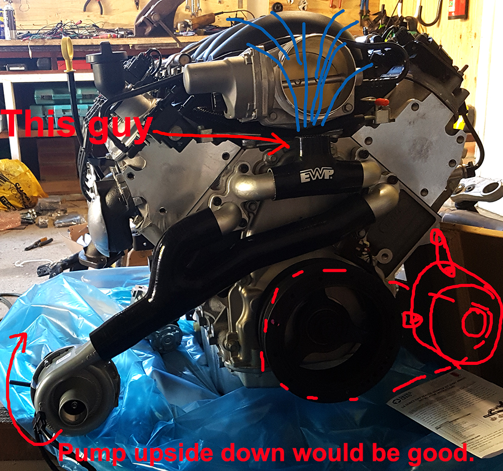
So there were a couple of issues ... the outlet at the top runs straight into the bottom of the throttle body (I guess they assume a carby setup, and one of the install pictures shows a carby intake manifold). I totally forgot about the throttle body when buying the install kit. I'll just rotate the outlet forward and use a 90 degree bend to try and keep the stick out as small as possible.
It would also be good to rotate the pump upside down so the inlet was facing towards the center line of the bike. I can't see any issue with doing that, but will ping them an email and ask just to be sure.
The bottom right is where I'll mount the alternator. I think I'll just make a bracket ... all the ones I've seen online so far assume all the other normal car stuff will be in place. And I think I'll run it off the inner 4 groove part of the pulley just to keep it a little more out of the breeze.
If anyone can see any issues, or has some advice for me, please let me know.
Cheers
My electric water pump showed up today, so I threw it on (without clamps or sealant) exactly as in the instructions just to see what was what:
So there were a couple of issues ... the outlet at the top runs straight into the bottom of the throttle body (I guess they assume a carby setup, and one of the install pictures shows a carby intake manifold). I totally forgot about the throttle body when buying the install kit. I'll just rotate the outlet forward and use a 90 degree bend to try and keep the stick out as small as possible.
It would also be good to rotate the pump upside down so the inlet was facing towards the center line of the bike. I can't see any issue with doing that, but will ping them an email and ask just to be sure.
The bottom right is where I'll mount the alternator. I think I'll just make a bracket ... all the ones I've seen online so far assume all the other normal car stuff will be in place. And I think I'll run it off the inner 4 groove part of the pulley just to keep it a little more out of the breeze.
If anyone can see any issues, or has some advice for me, please let me know.
Cheers
-
russelllowe
- Posts: 252
- Joined: Mon Jan 06, 2014 2:21 pm
- Contact:
Re: theTRUTH
So ... I might be getting old, or conservative, or both ... but this is version 3 of theTRUTH (in a very, very, sketchy 3ds Max Model):
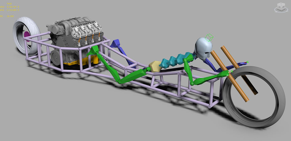
As you can see, its a pretty conventional riding position now. With how high it has become at the front, and the height of the motor it seems I could choose between feet forward and head forward without much difference in frontal area. It's about 5.5 square feet in frontal area, which is pretty not much. I was disappointed about going so wide (being dictated by accessories on the front and depth of the oil pan at the rear) but after seeing that number I cheered up quite a bit.
Going head forward also throws a bit of weight forward too ... which will help with shifting the center of mass forward of the center of drag. Also simplifies the steering, while making it a bit more normal to ride.
The tubes are shown as 1.25" , which I have the bending dies for, so some of the junctions will be bent. And I think I'll go for 3mm wall thickness (where 2mm would probably do) because it wont move so much when I weld it. And the extra strength wont hurt.
I think I'll use some diaphragms for extra bracing here and there.
Here's a question: has anyone (who can be bothered reading all this) used a water tank instead of a radiator? I'm thinking a large'ish water tank between my legs and above the frame rails (or under my chest, within the frame rails) might also help with shifting the weight forward.
Cheers
-
Hoofhearted
- Posts: 62
- Joined: Wed Nov 25, 2009 5:55 pm
- Location: Riverside, SoCal
Re: theTRUTH
A lot of cars run water tanks rather than a radiator. Most of them seem to use the tank as ballast and / or weight distribution. If you go head first you might take a look at Mark Bjorklund's twin Ducati. He is a big fan of duplex steering and it does make for a very tidy and low front end.
https://youtu.be/2OtVLm3D6Is
https://youtu.be/2OtVLm3D6Is
Don't cry because its over. Smile because it happened.
Re: theTRUTH
I recongise you now lol,,
Looking at the sketch above,, rule of thumb is that with bodywork 6* is a good closing angle on the tail,, given the width of the engine/chassis, you may have to place the rear wheel further back to achieve this,,
Looking at the sketch above,, rule of thumb is that with bodywork 6* is a good closing angle on the tail,, given the width of the engine/chassis, you may have to place the rear wheel further back to achieve this,,
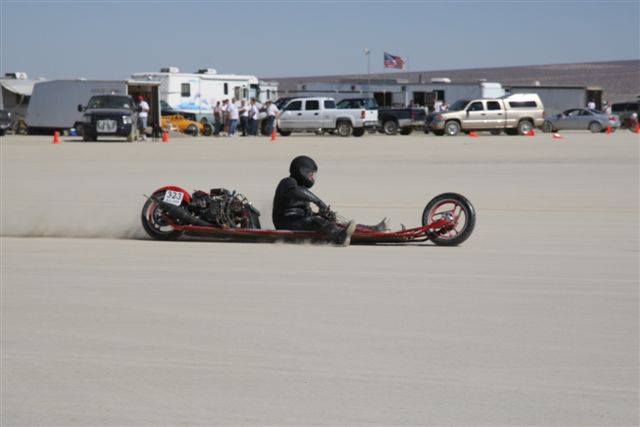
First Australian to ride a motorcycle over 200mph at Bonneville,,,
-
russelllowe
- Posts: 252
- Joined: Mon Jan 06, 2014 2:21 pm
- Contact:
Re: theTRUTH
Hoofhearted, yeah that's what I was thinking ... think that's the way I'll go, right up front under my chest. Yup, seen Mark's bike run at Bonneville ... in 2014 when the conditions were pretty sketchy (didn't effect me on the CB750, but loads of high horsepower bikes were struggling to go over 175) ... after what I think was his fastest run (192 I think) I asked him how it went and he said "scary". I said, "scary in a good way?" and he was quite clear the answer was no, not good at all. Apparently the tail started wagging and he thought he might give it a bit more to see if it straightened out ... which just made it worse. He's gone over 200mph since, so I think the salt played a large part in it, but I have the throwing dart principle in my head which is guiding my thinking re ballast. Marks Duke is really long with both motors close to the rear.
I like his steering setup, but according to Tony Foale it will suffer from the same thing as the Budfab linkage setup ... the more it turns the more it wants to turn. Carl's new straight 6 cylinder Honda uses the same design again, but much larger than Mark's for some reason. He is @thesuperrat on Instagram if anyone wants to take a look. It's a very cool build. Style for days.
Staytie, yeah that's me! My APSG1000 fairing followed the 6 degree closing angle (the Vellocette guys gave me that tip). It had quite a Kamm tail on it because of the width of the frame at the rear axle. I've just moved the rear wheel back to accommodate the 600mm swing arm I'll probably use (off the GSXR1000) and a bit more because the standard headers needed more room too.
Updated pic:
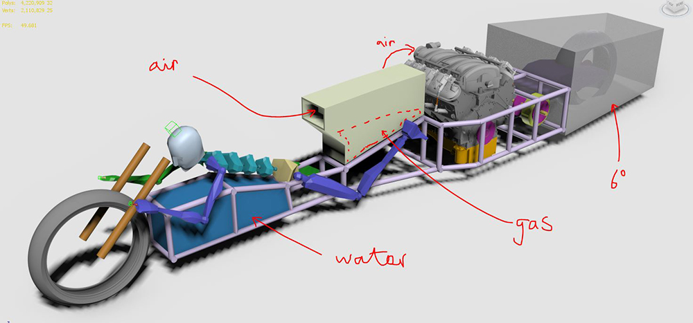
Still pretty wide at the rear ... but I can only go 10" back from the rear of the rear tire, so I guess that's what I get. Most likely still be running naked is 2018 anyway.
A key objective is to make sure I have the wheels aligned before I go this time ...
Cheers
I like his steering setup, but according to Tony Foale it will suffer from the same thing as the Budfab linkage setup ... the more it turns the more it wants to turn. Carl's new straight 6 cylinder Honda uses the same design again, but much larger than Mark's for some reason. He is @thesuperrat on Instagram if anyone wants to take a look. It's a very cool build. Style for days.
Staytie, yeah that's me! My APSG1000 fairing followed the 6 degree closing angle (the Vellocette guys gave me that tip). It had quite a Kamm tail on it because of the width of the frame at the rear axle. I've just moved the rear wheel back to accommodate the 600mm swing arm I'll probably use (off the GSXR1000) and a bit more because the standard headers needed more room too.
Updated pic:
Still pretty wide at the rear ... but I can only go 10" back from the rear of the rear tire, so I guess that's what I get. Most likely still be running naked is 2018 anyway.
A key objective is to make sure I have the wheels aligned before I go this time ...
Cheers
-
simpleterm

- Posts: 15
- Joined: Sun Sep 10, 2017 12:14 am
Re: theTRUTH
I'm interested in following this, I hope you'll post more pictures and maybe even videos! Do you have any idea how much it will cost to build in the end?
Re: theTRUTH
Regards your pump orientation its no problem upside down, alternator on its own only needs a 3pk belt. (less frictional loss) Be aware when bleeding the system your change to the pump position but they self bleed ok.
Chris
Chris
Chris